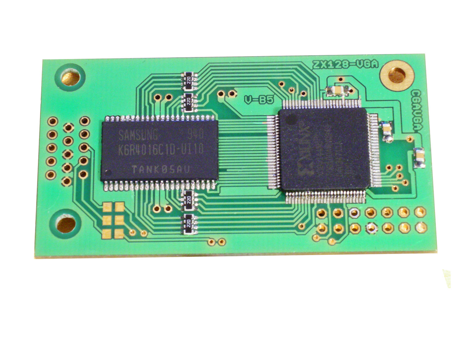
| STEP 1 solder all smd components (sram,cpld,resistors,capacitors) |
 |
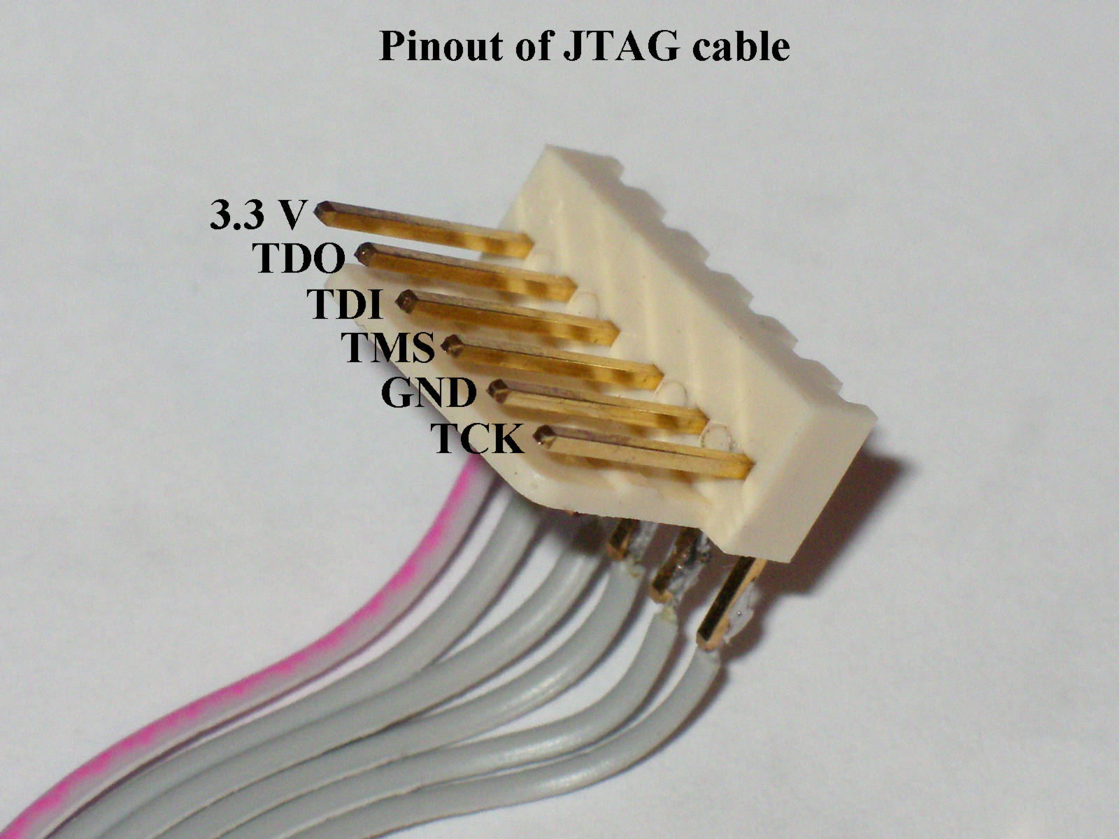
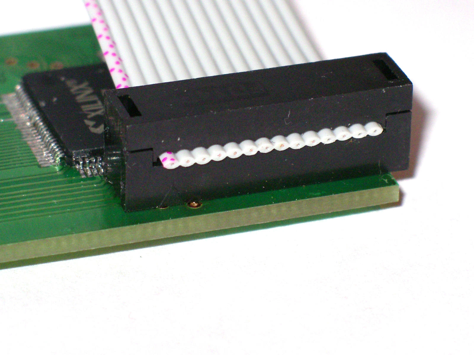
| STEP 2 connector for cable |
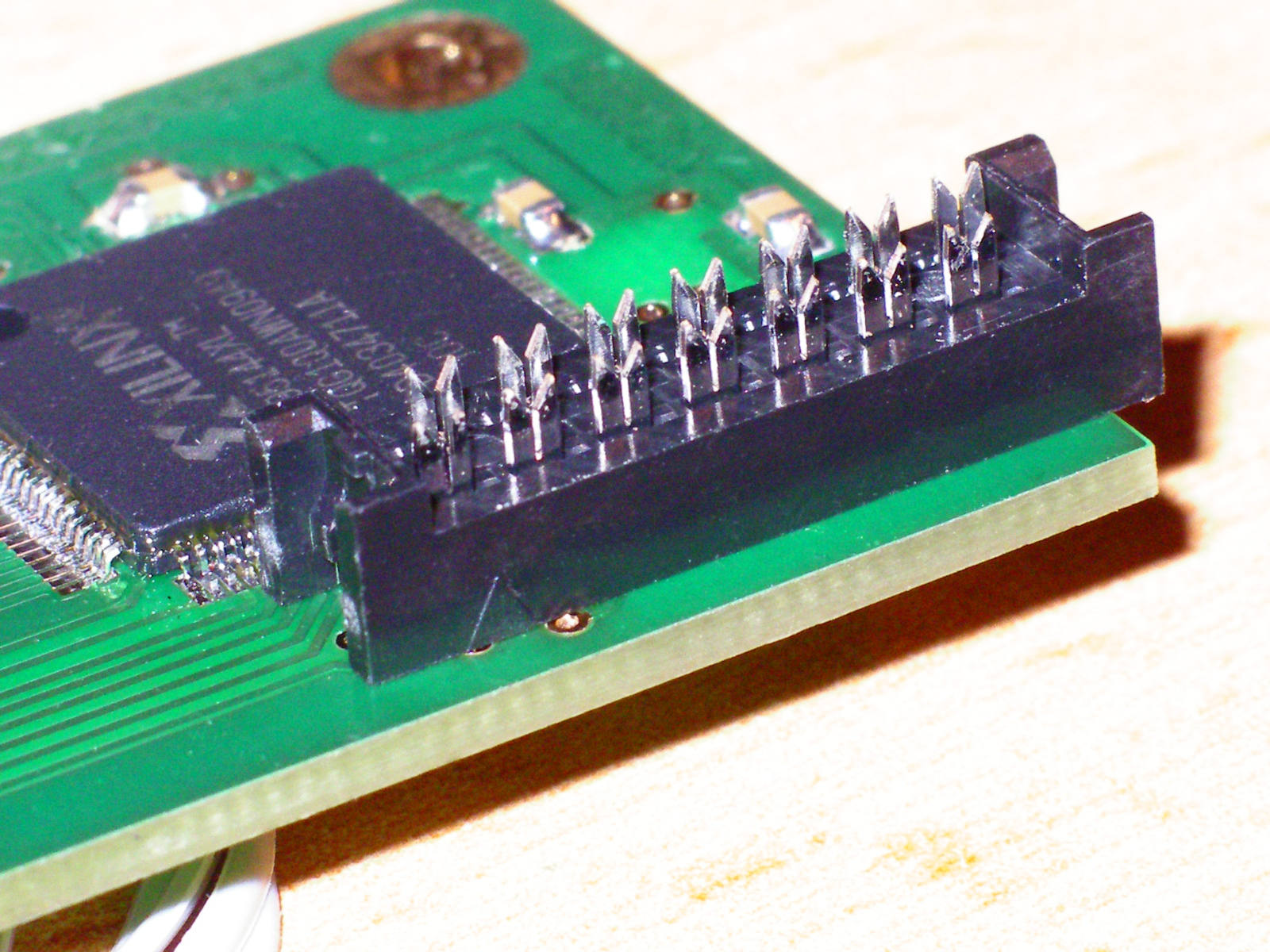 |
| STEP 3 connect cable to connector |
 |
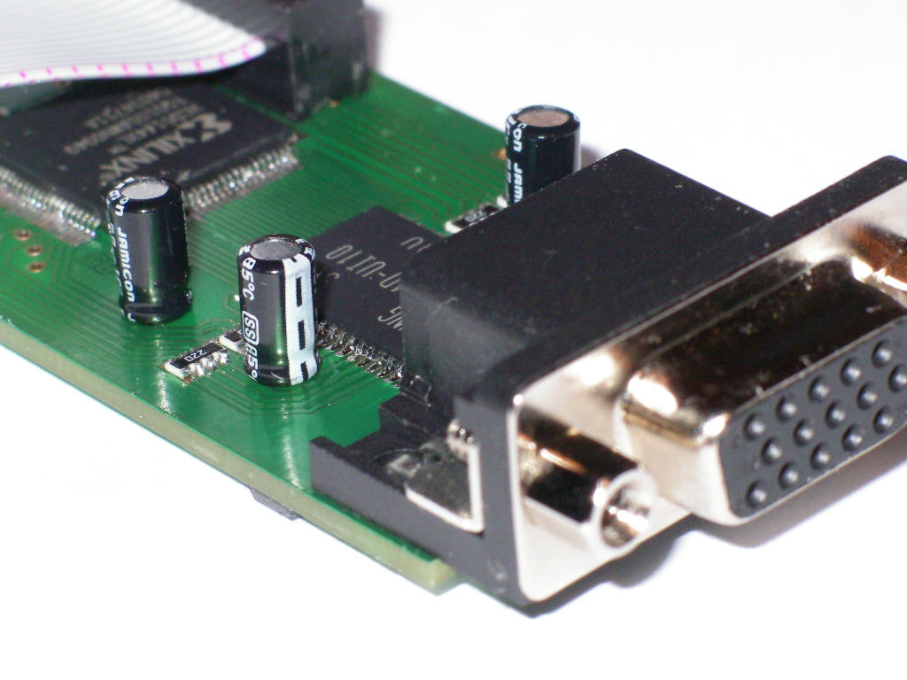
| STEP 4 VGA connector and capacitors |
 |
| detail of VGA connector |  |
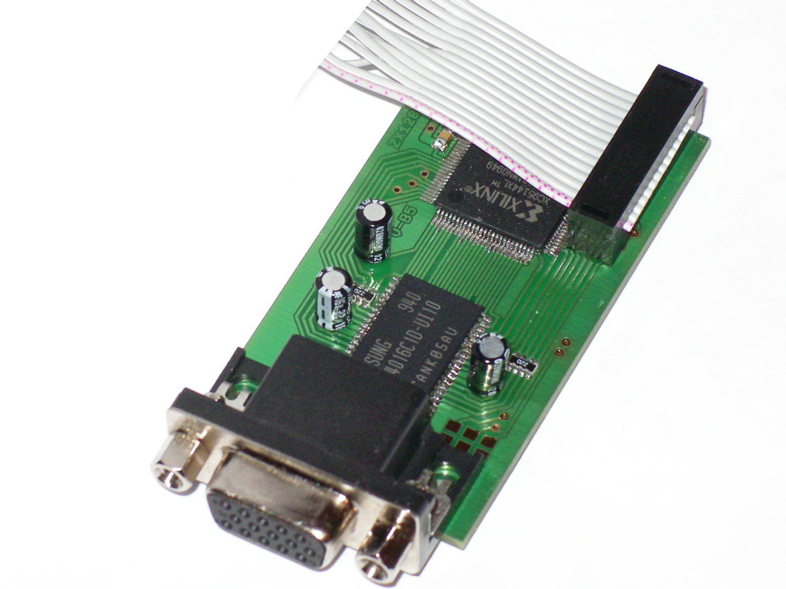
| 3D view please connect correct polarity on electrolytic capacitors |
 |
| 3D view please connect correct polarity on electrolytic capacitors |
 |
| detail - sram memory | 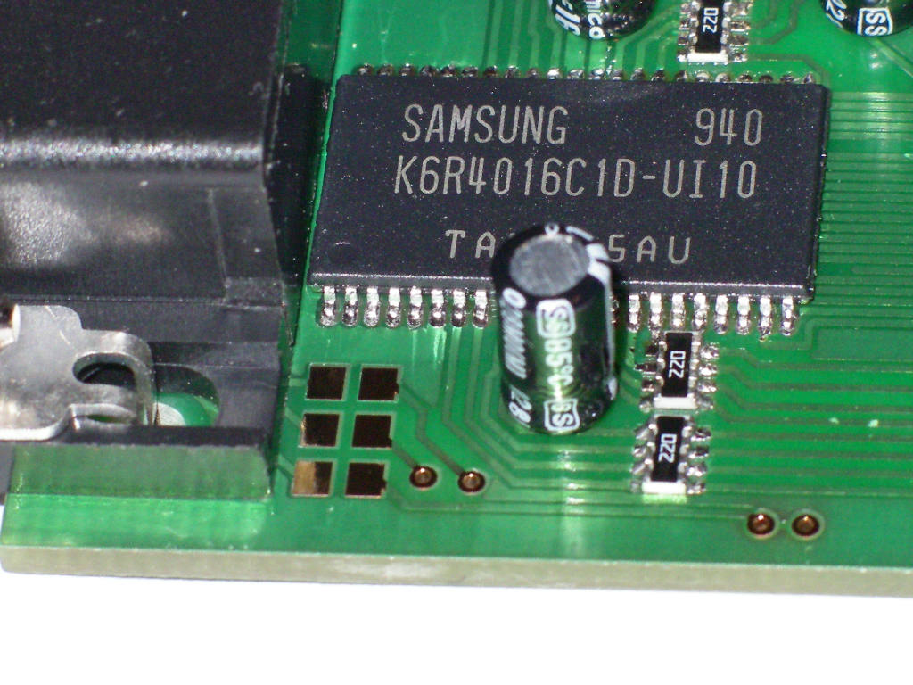 |
| components side | 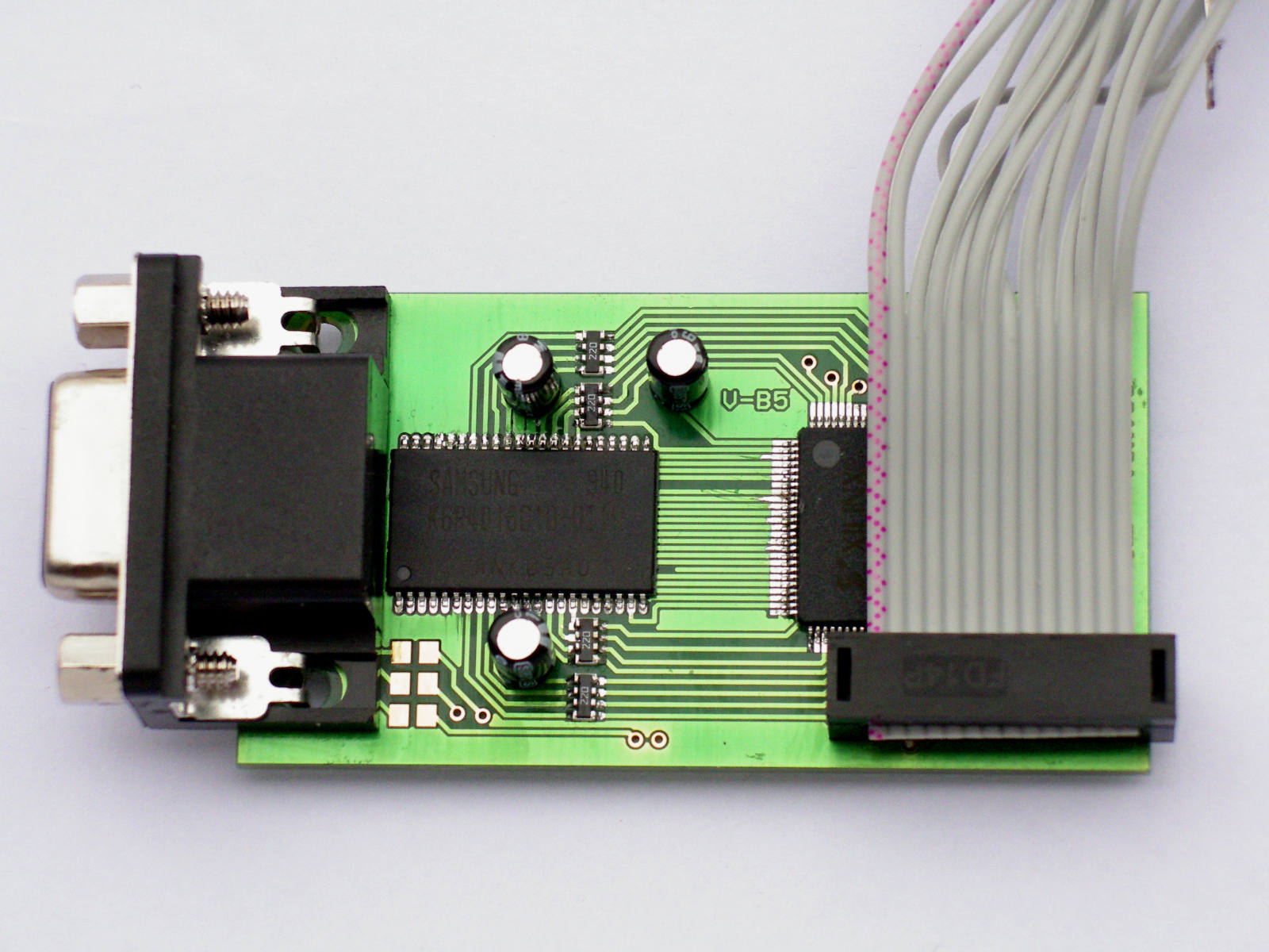 |
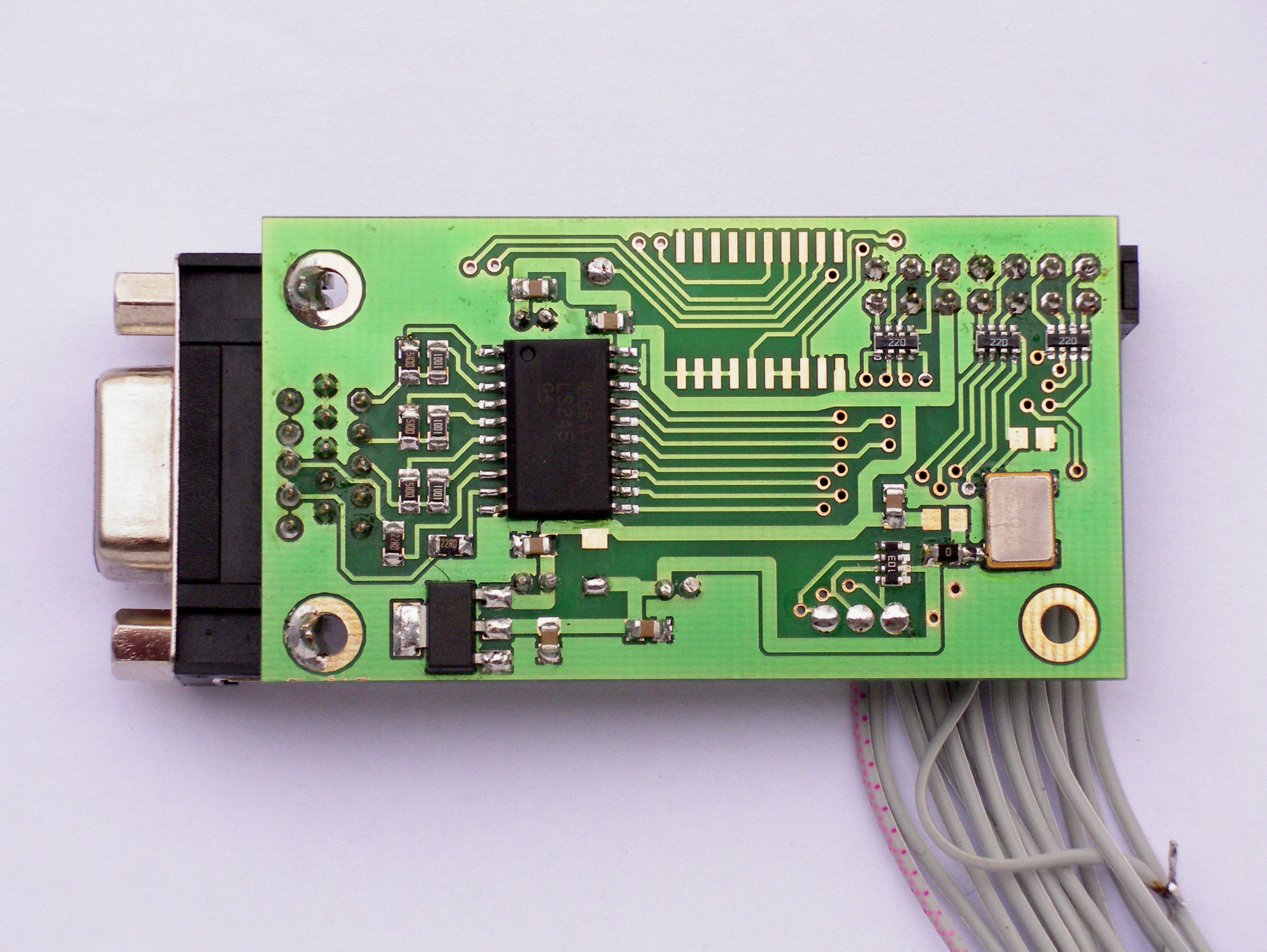
| STEP 5 solder 74LS245, voltage regulator, crystal oscillator, capacitors, resistors |
 |
| detail of crystal oscillator | 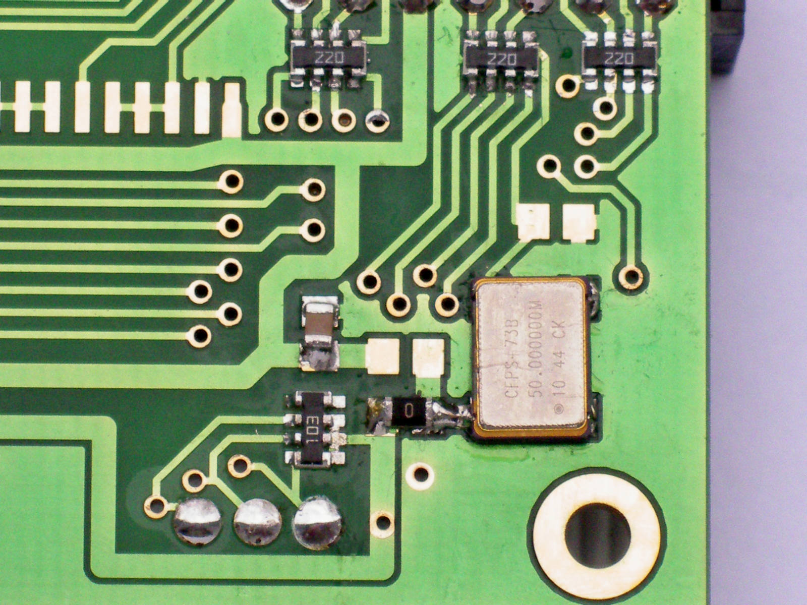 |
| detail of voltage regulator | 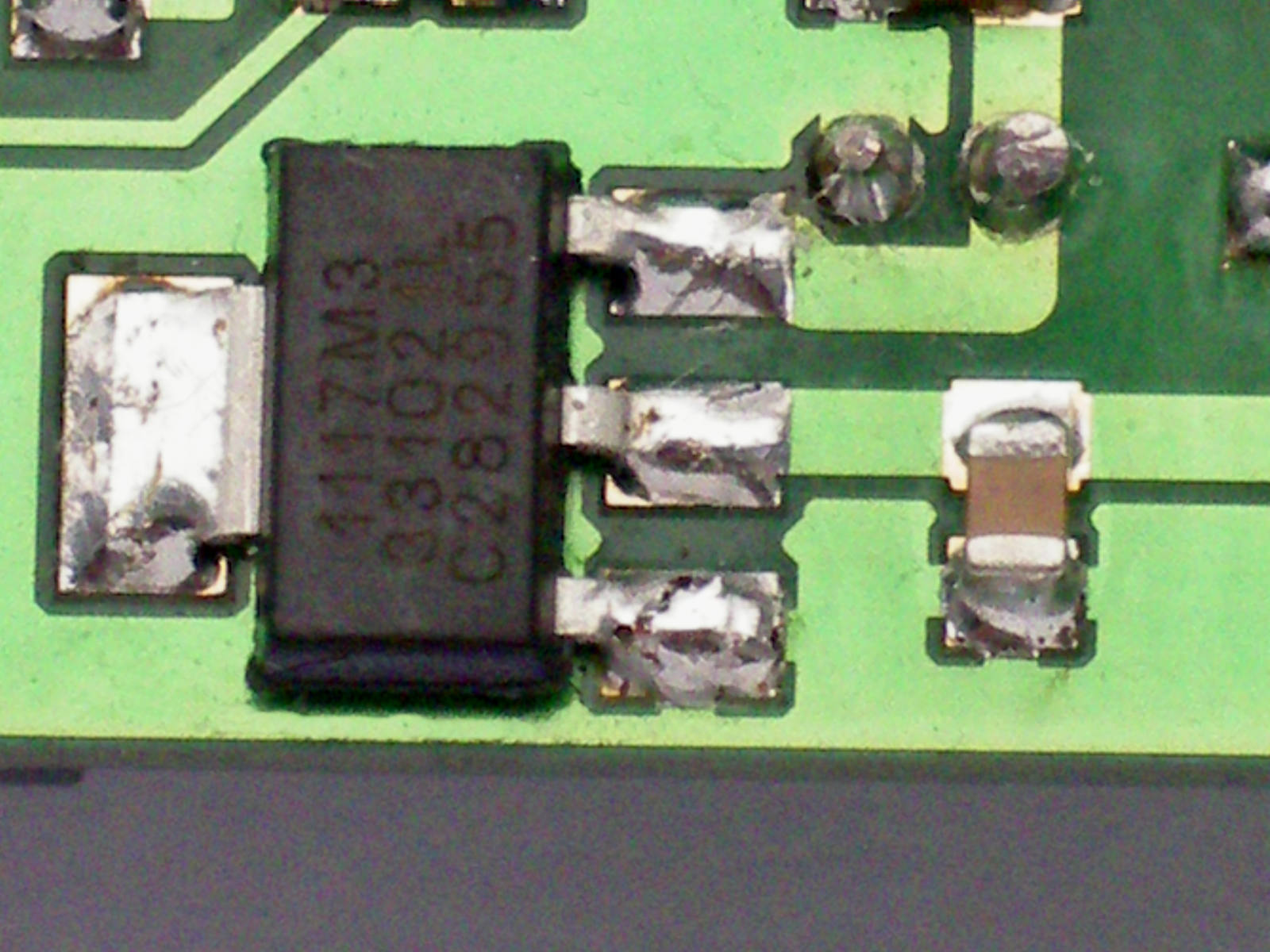 |
| next detail | 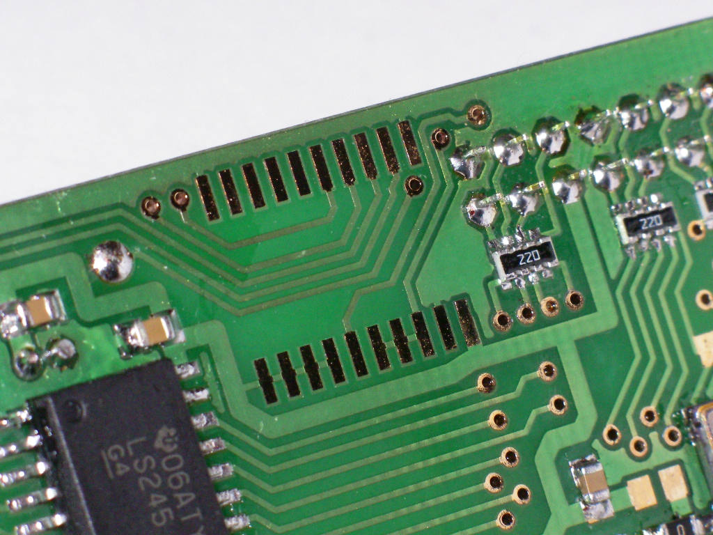 |
| detail of 74LS245 and resistors for mixing RGB signals for VGA output | 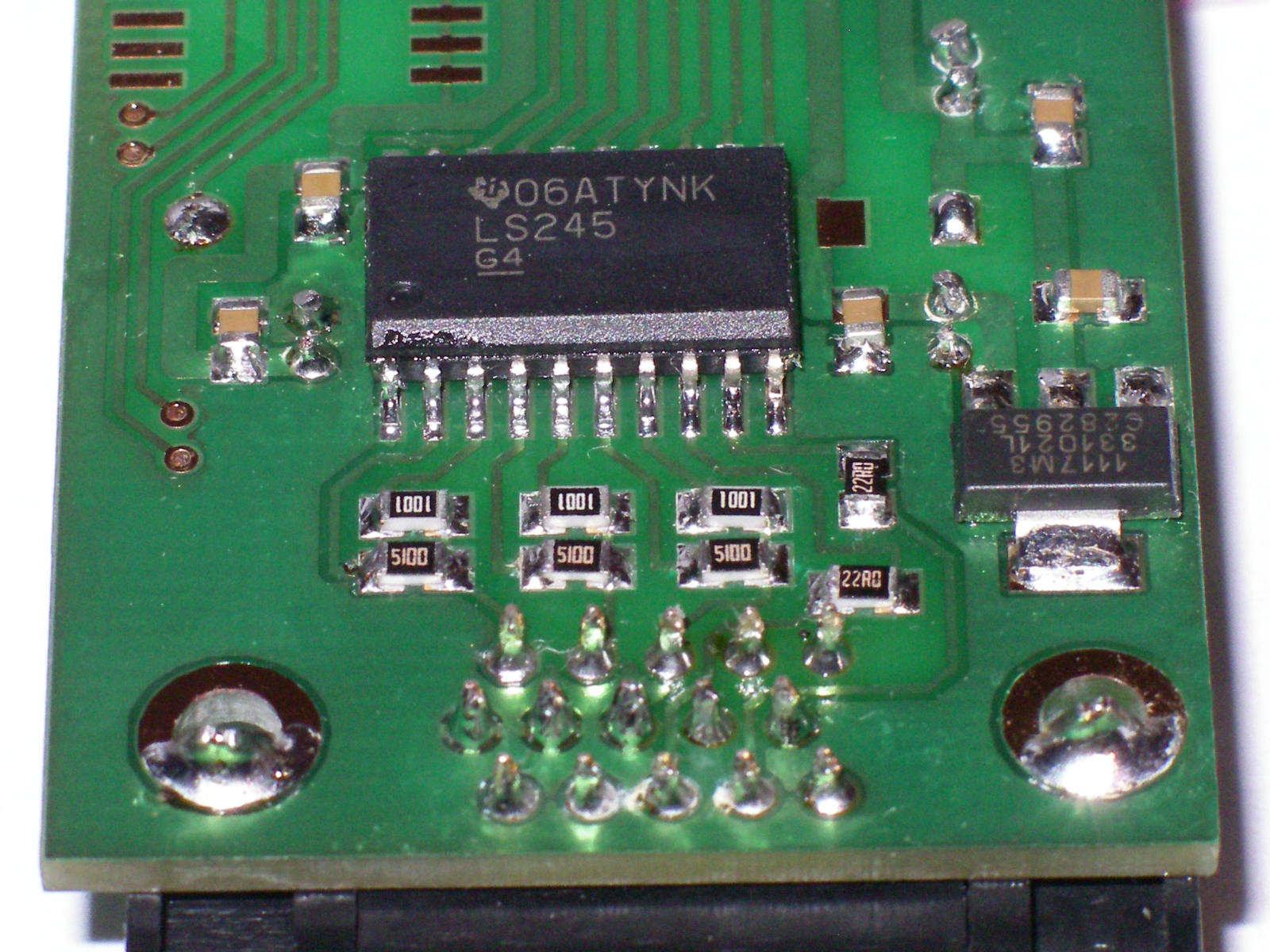 |
| tetail of bottom side of cable connector, resistor nets, oscillator | 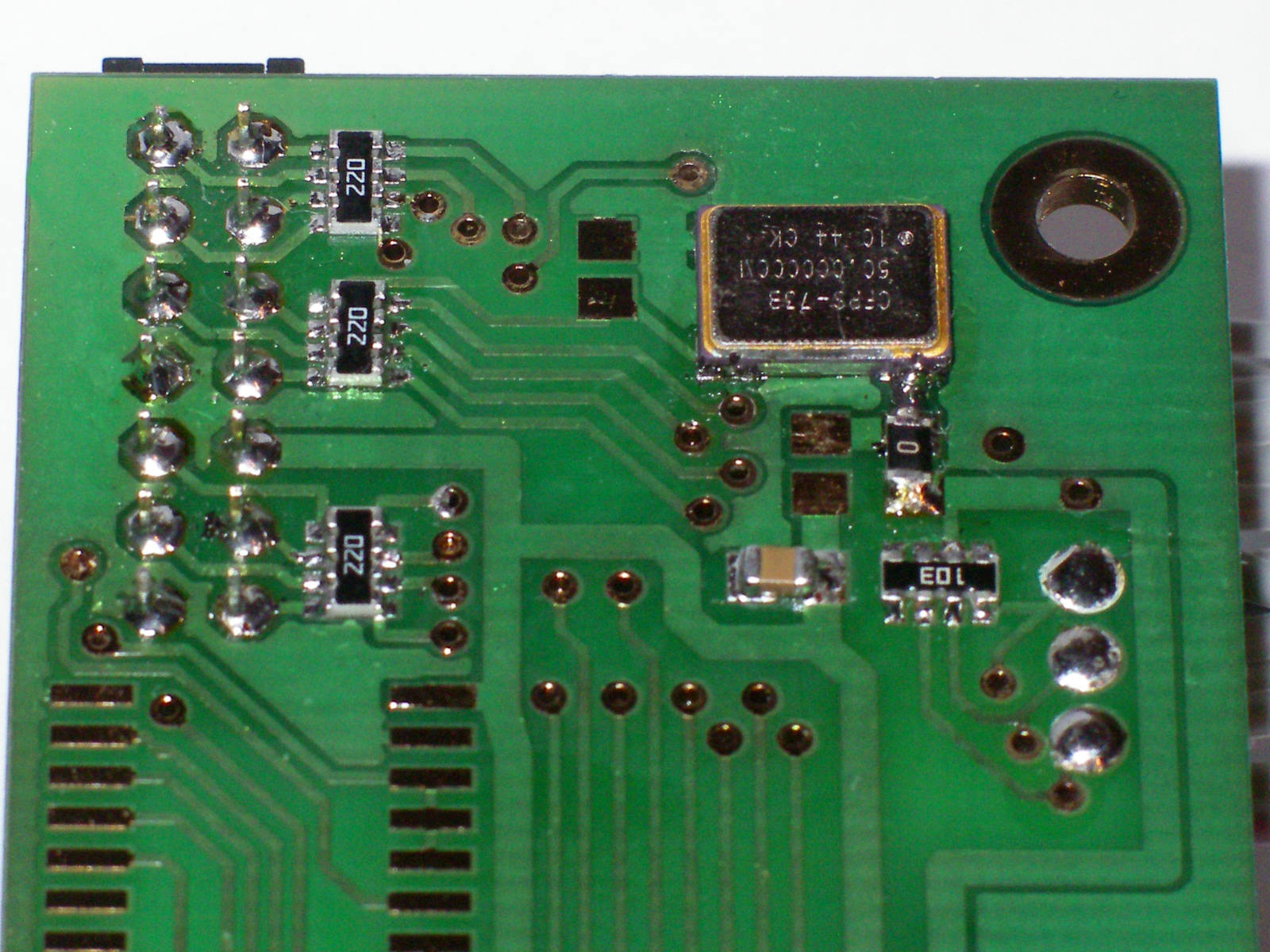 |