|
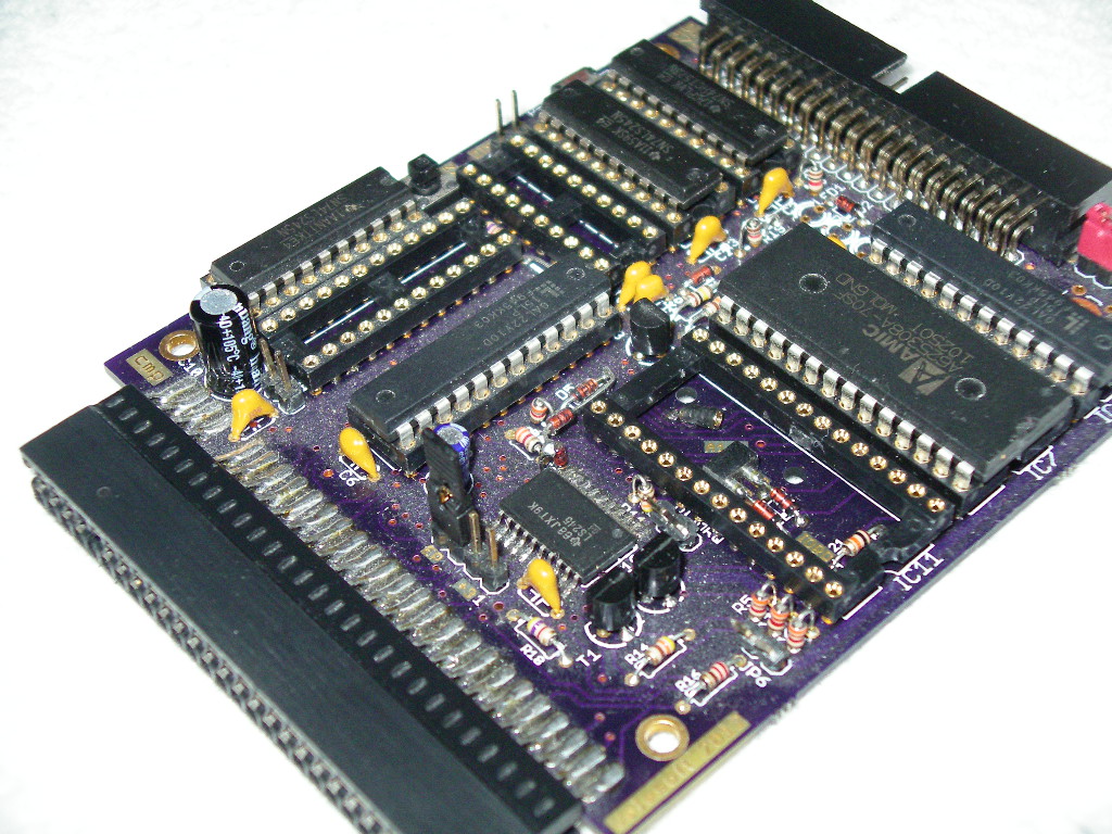
STEP 1 - remove from sockets on original divide
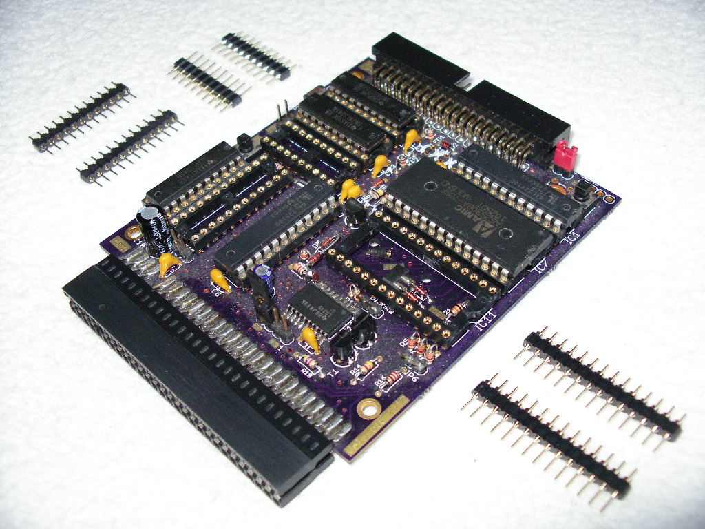
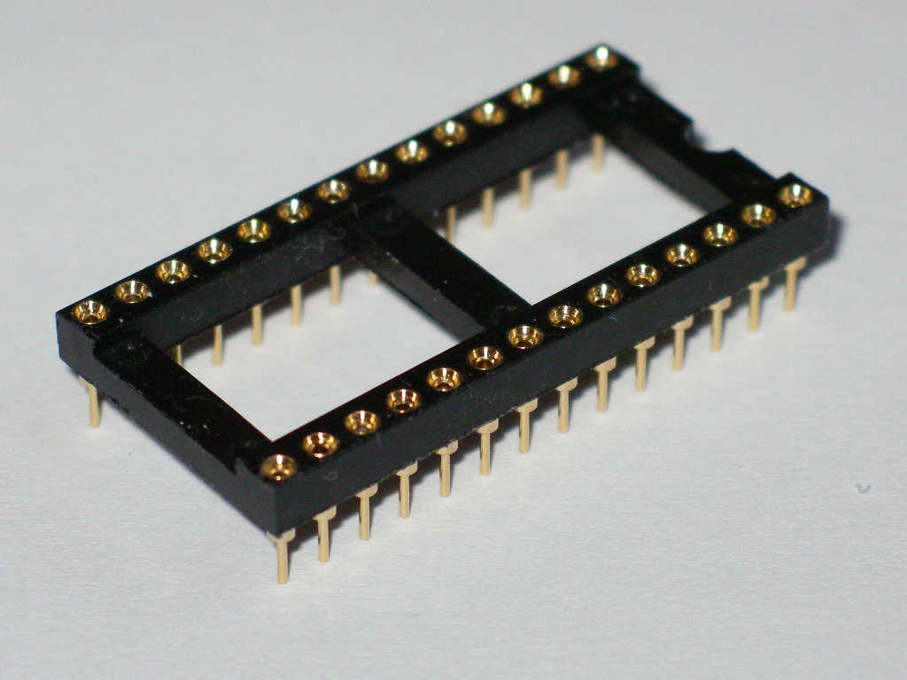
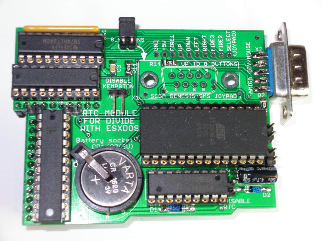
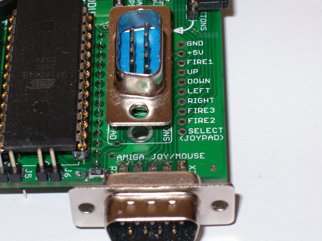
interface this chips: M_GAL, EEPROM (AT28C64) and 74LS245 STEP 2 - you will need this pins for connect to
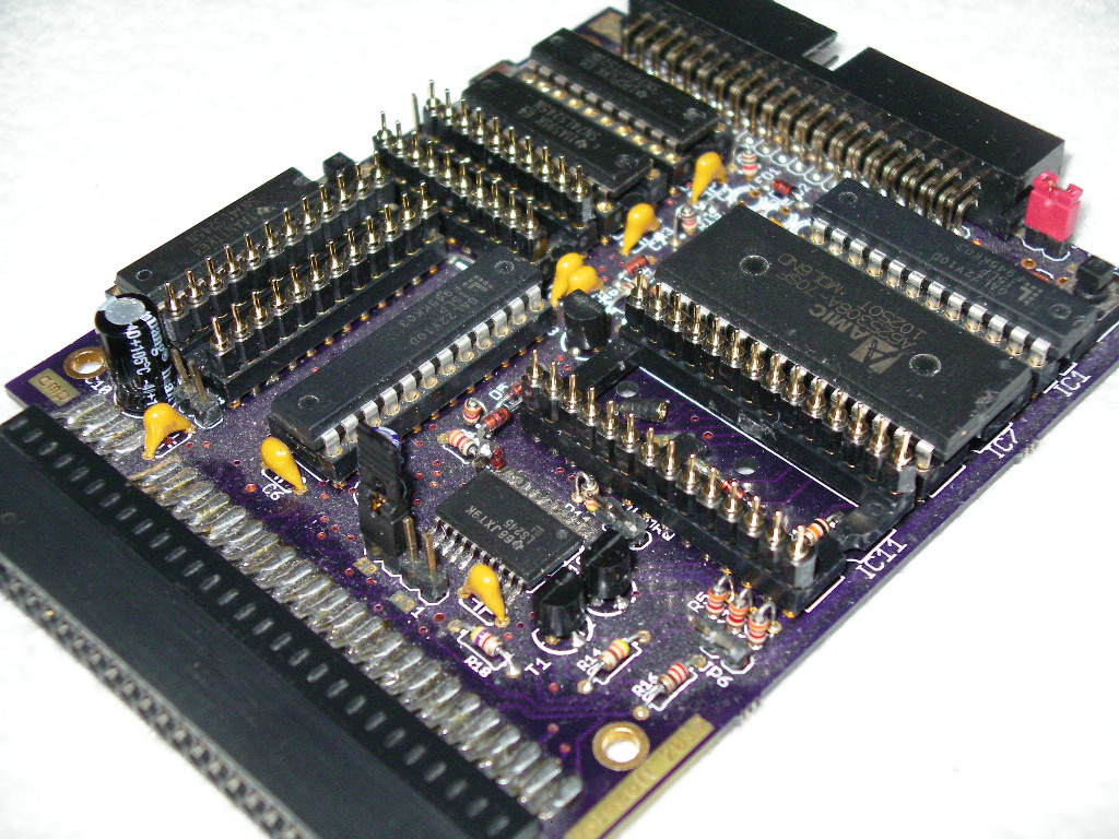
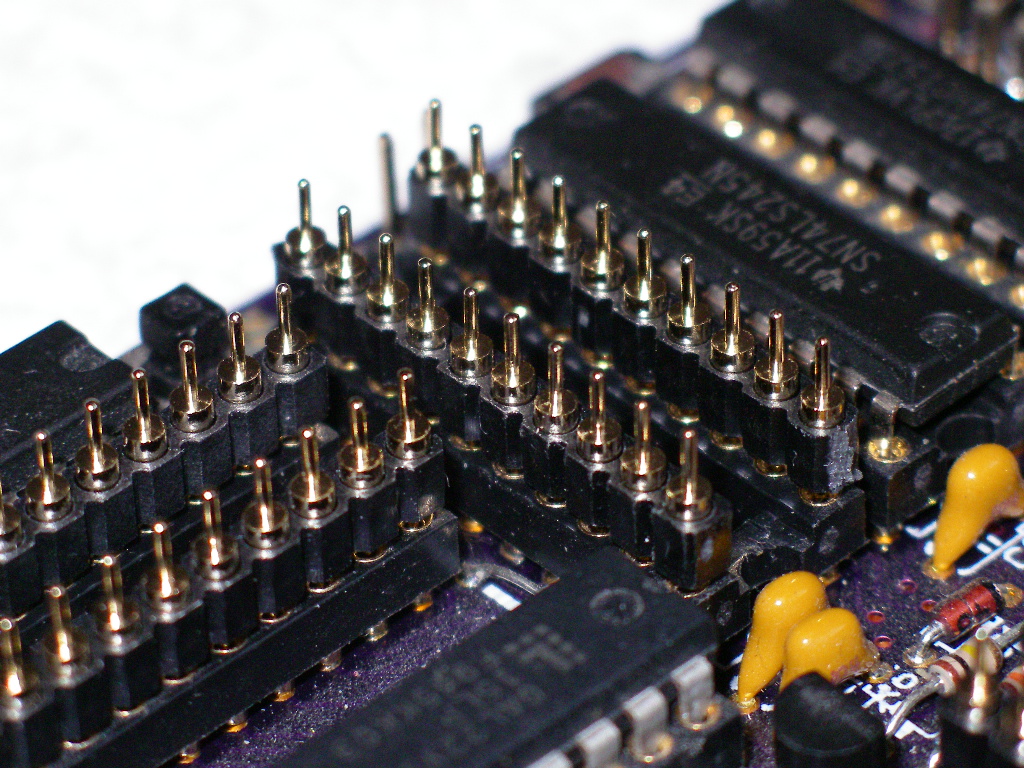
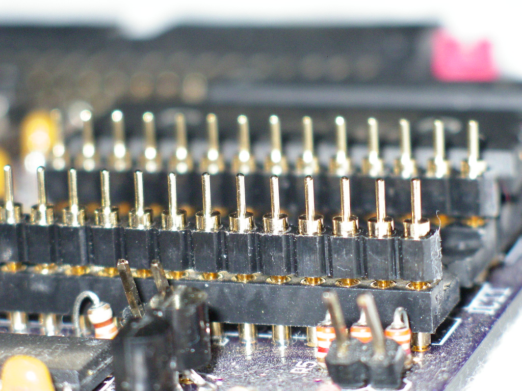
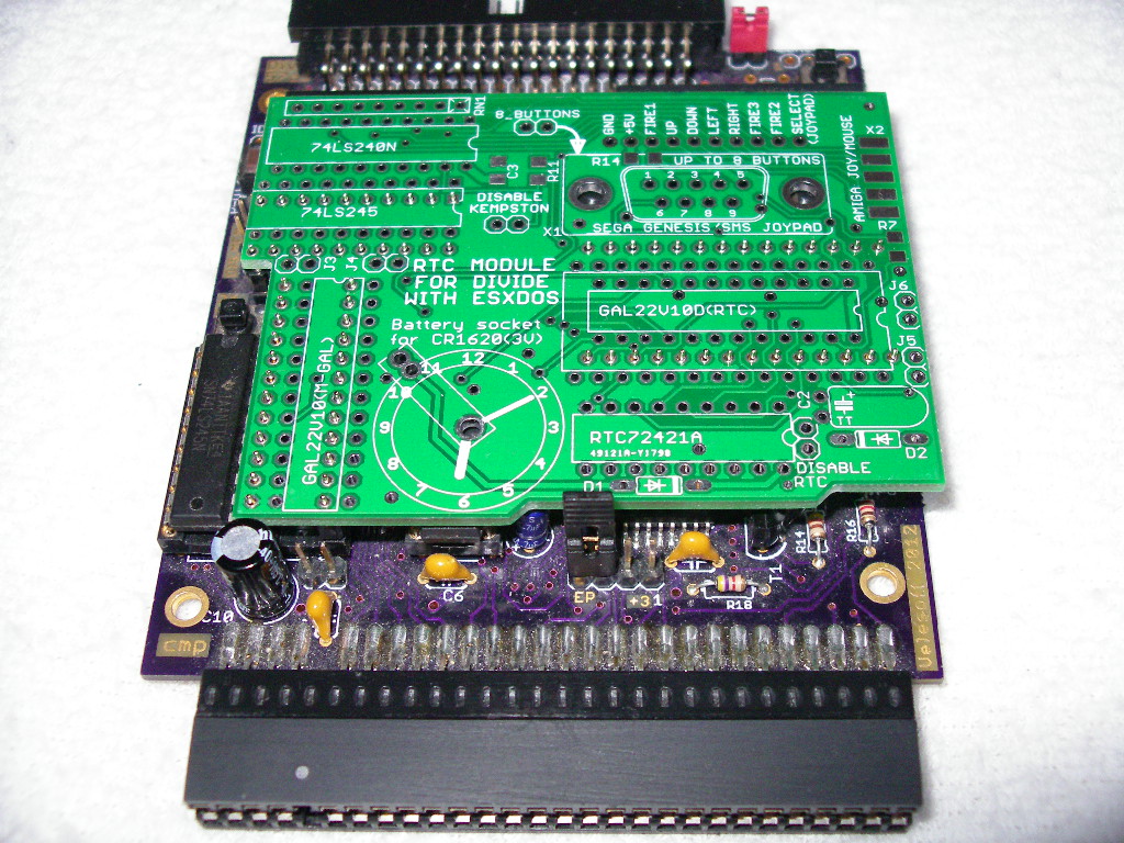
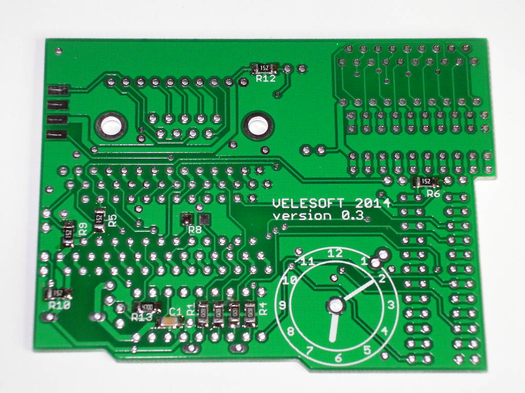
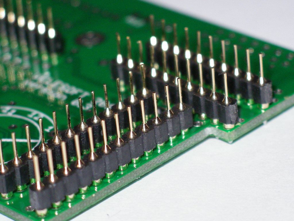
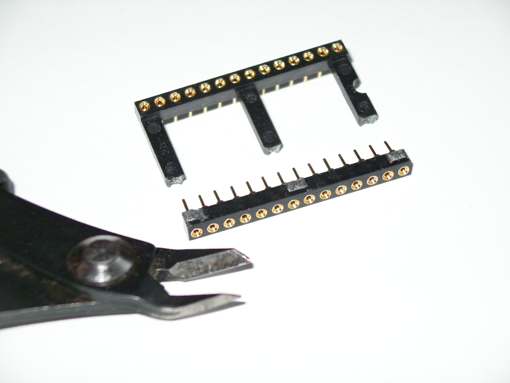
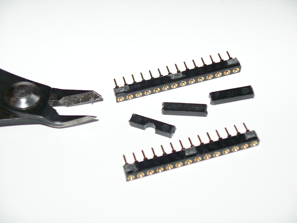
sockets (2x12 pins, 2x10 pins, 2x14 pins) STEP 3 - connect pins to sockets Detail of pins STEP 4 - connect PCB to pins STEP 5 - after solder pins disconnect PCB from divide Bottom side of PCB with soldered pins Detail Now we will modify new socket 28 pins STEP 6 - solder pin rows (2x14 pins) and three new
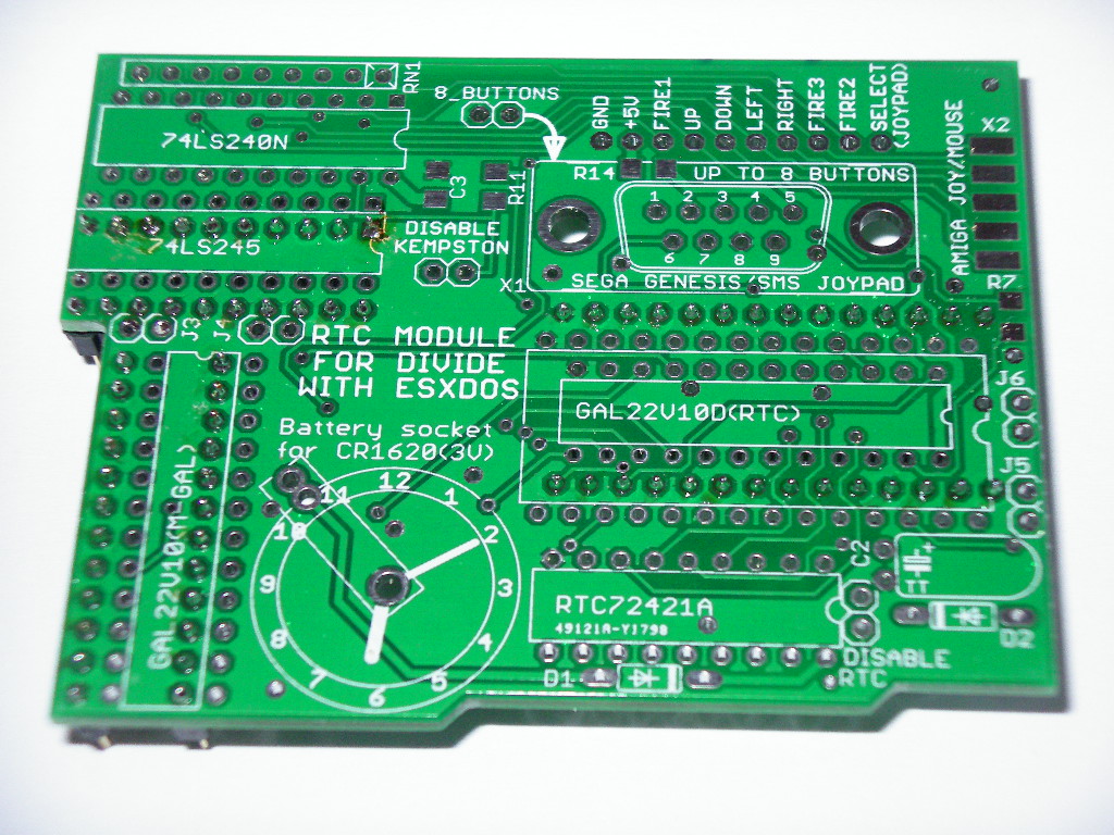
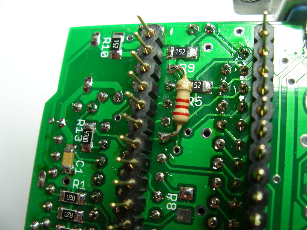
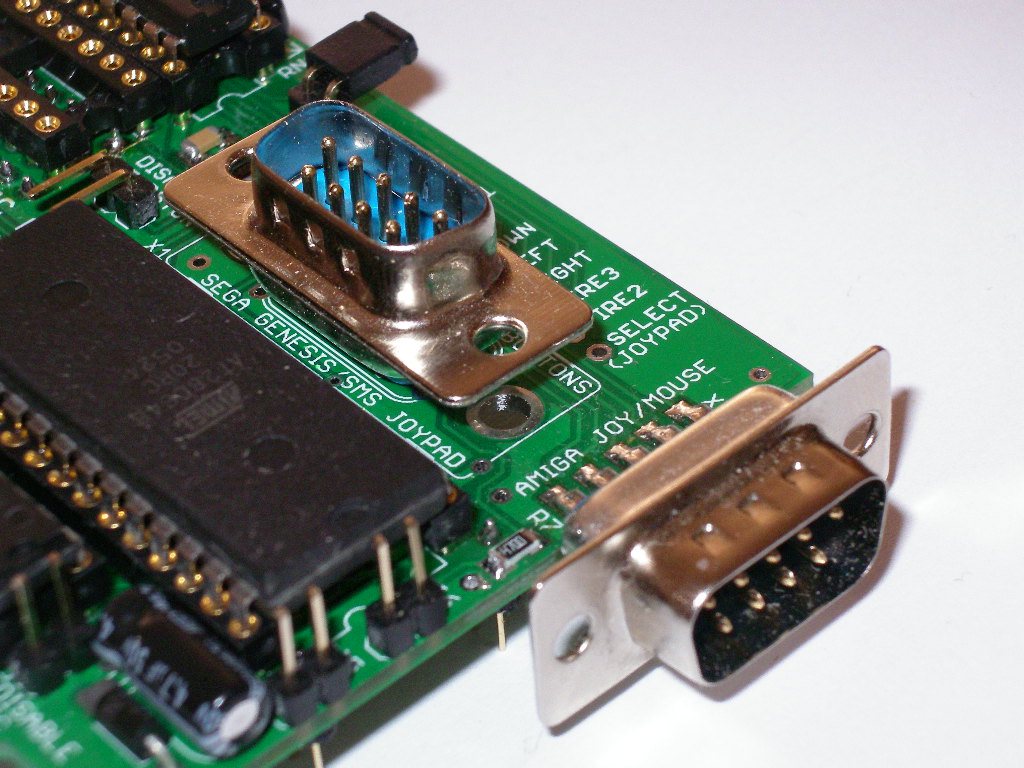
sockets (20pins,20pins and 24 pins) STEP 7 - solder all components on top side On bottom side you need connect resistor 2k2 between
pins 24(+5V) and 20(rtc_cs) on gal22v10(under eeprom socket). And
resistor R8 can be unused.
|